Gapless Reflector Hovermans
| Antenna Overview |
| VHF (2m/MURS) |
| Moxon Rectangle |
| Yagi-Uda |
| High-Gain Omni |
| UHF (70 cm) |
| Dual-Rectangle |
| HDTV |
| Hoverman |
| Gapless Hoverman |
| Extended Hoverman |
| jed |
| S-Lang |
| most |
| Complex Domain Coloring |
| SLxfig |
| Antennas |
| Thermochron |
| Main Page |
The designs presented on this page are Hoverman-style HDTV antennas that utilize a gapless reflector making them easier to build than my revison-2 designs. Two versions are presented here: a single bay design utilizing 12 reflector rods, and a double bay version consisting of 16 reflector rods.
Performance Predictions
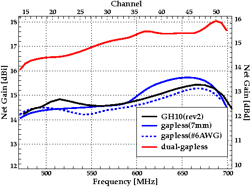
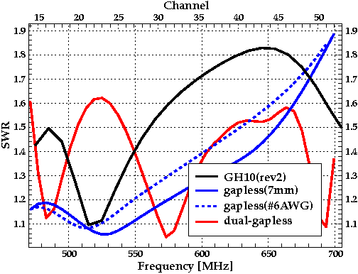
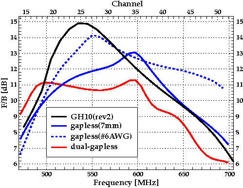
As the following plots show, the performance of the single bay gapless version is quite close to that of the revision-2 GH10. Being about twice the height, the double-bay variant is expected to have a gain of about 2.5 dB over the single bay versions.
Specifications
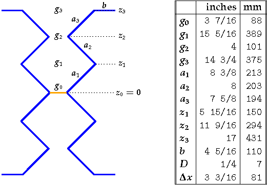
The geometric parameters of the were found by the optimization process outlined on the Antenna Overview page. Each antenna consists of two parts: a driven element formed by a zigzag pair, and a reflector made up of a varying number of horizontal parasitic elements.
The figures and tables provided below give the detailed geometric information about the antennas. The measurements have been rounded to the nearest 16th of an inch, as well as to the nearest mm. Each of the tables contains a ``D'' parameter, which represents the diameter of the wire to be used. In addition, the tables for the zigzag driven element contains a `` Δx'' entry that represents the spacing between the driven element and the reflector. The `` Δz'' values that appear in the reflector geometry tables represent distances between adjacent reflector rods. For example, z2 = z1 + Δz1. (The symbol Δ is commonly used in mathematics to signify a difference between two values. In this case Δz1 = z2 - z1.)
The feedpoint, denoted by the orange segment connecting the zigzag pairs, has a 300 ohm impedance. As such, a 300 ohm matching transformer will be required to connect this to standard 75 ohm cable (RG-6).
Two versions of the single bay gapless designed are provided below. Both versions use 7mm (1/4 inch) diameter rod for the reflector elements. They differ only in the diameter of the wire to be used for the zigzag driven elements (7mm vs #6 AWG).
Single Bay Parameters (7mm)
Single Bay Parameters (#6 AWG)
Double Bay Parameters
NEC-2 Files
In this section, links are provided to the NEC-2 files for the above designs. These files require a version of NEC-2 that is able to read geometry lines that consist of more than 80 bytes. Standard versions of NEC-2 are not able to do this and may produce a geometry card error when used with these files. I use a version of nec2dx that I modified to read geometry cards up to 256 characters in length.
NEC-2 file for the single bay 7mm gapless