A 2 element dual-rectangle beam for 70cm
| Antenna Overview |
| VHF (2m/MURS) |
| Moxon Rectangle |
| Yagi-Uda |
| High-Gain Omni |
| UHF (70 cm) |
| Dual-Rectangle |
| HDTV |
| Hoverman |
| Gapless Hoverman |
| Extended Hoverman |
| jed |
| S-Lang |
| most |
| Complex Domain Coloring |
| SLxfig |
| Antennas |
| Thermochron |
| Main Page |
The antenna described here is a direct-connect dual-rectangle beam for use on 70 cm between 440 and 450 MHz. The basic geometry of the antenna is shown in the following figure:
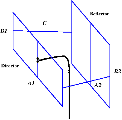
An interesting feature of this antenna is that both dual-rectangular elements are electrically connected together, so strictly speaking, the antenna is a single monolithic structure. It was designed this way to simplify and minimize the support structure for the antenna.
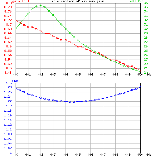
This antenna was optimized using NEC-2 to have a front-to-back ratio in excess of 20 dBi and an SWR of less than 1.3 from 440 to 450 MHz when used with a 50 ohm feedline. As the .nec file shows, an attempt was made to take into account the effects of feedline radiation by including the feedline as extra wire elements connected to one side of the source.
The resulting geometric parameters were determined to be
       A1       18 5/16 in.
       B1        3 15/16 in.
       A2       14 1/8 in.
       B2        6 3/4 in.
        C        6 in
        D        5 5/8 in.     (director-reflector distance)
       Wire     #14 AWG
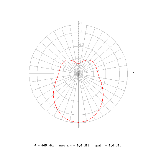
The predicted radiation pattern is shown in the traditional ARRL style and was generated from the final design by xnecview.
Here are plots of the predicted SWR, Gain, and F/B ratio as a function of frequency:
It took me about 2 hours to build the antenna using #14 AWG wire and PVC pipe. Here is a picture of the resulting antenna:
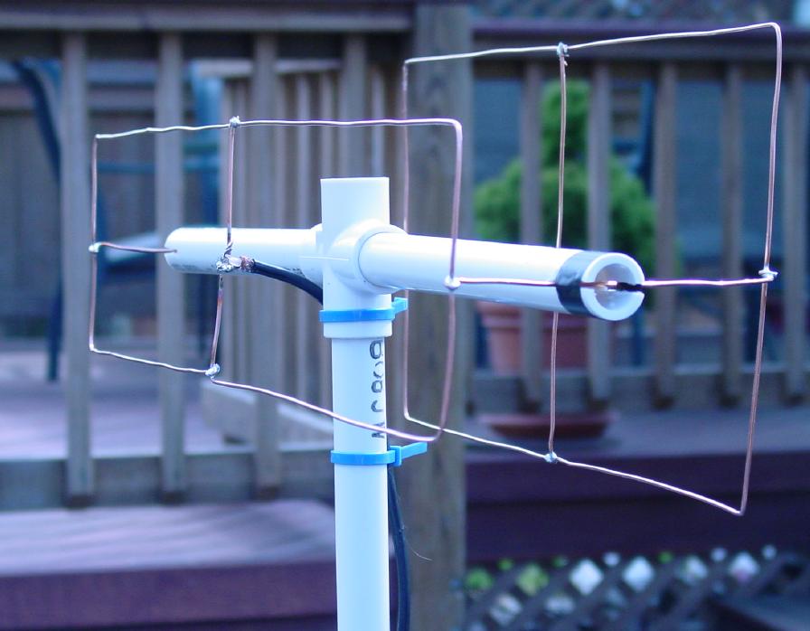
Note that the coax is directly connected to the antenna with no choke nor balun. As stated earlier, the antenna was designed taking feedline radiation into account.
Unfortunately, I did not have the equipment to test the characteristics of the antenna. All I had on-hand to make quantitative tests was an old uncalibrated ``micronta'' field strength meter. So I set up a ``test area'' in the driveway to measure the radiation pattern with the field-strength meter. Here is a picture showing the test area:
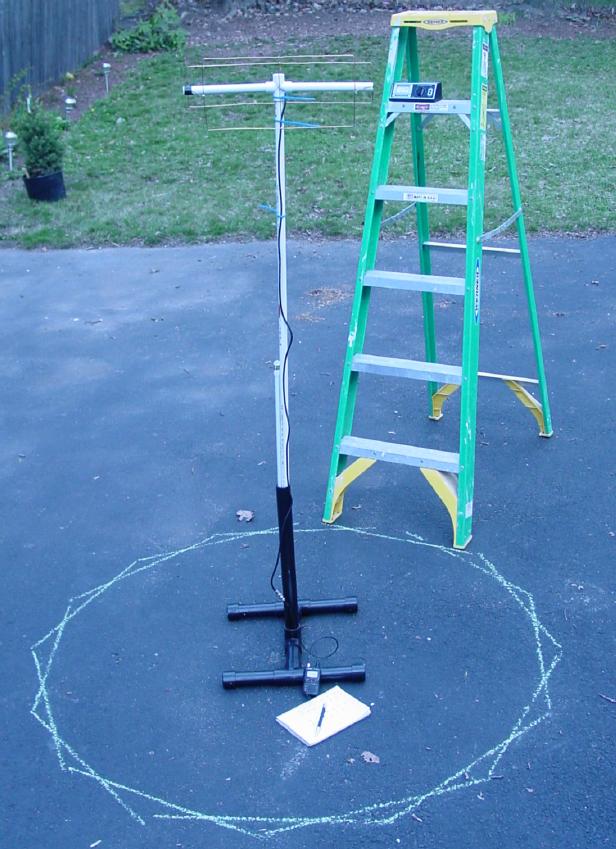
The picture shows the field strength meter on one of the steps of the fiberglass+aluminum step-ladder. It also shows two intersecting octagons centered upon the position of the antenna mast. These octagons were used to position the step ladder at 16 different angles and at more or less the same distance from the antenna.
The meter scale has field-strength values running from 0 to 5. The deflection was adjusted to measure 5 in the forward direction. Here is a plot of the resulting field strength measurements rounded to the nearest half-unit. I estimated the errors in the measurements to be about 1/4 of a field strength unit.
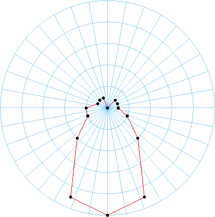
It would have been nice if I had had some sort of a reference antenna to compare. The best I was able to come up with was a Comet SMA-24 (17 inch dual-band duck). Standing at the center of the octagons, the Comet antenna was at best able to produce a field strength reading of about 1.