A Moxon for MURS
| Antenna Overview |
| VHF (2m/MURS) |
| Moxon Rectangle |
| Yagi-Uda |
| High-Gain Omni |
| UHF (70 cm) |
| Dual-Rectangle |
| HDTV |
| Hoverman |
| Gapless Hoverman |
| Extended Hoverman |
| jed |
| S-Lang |
| most |
| Complex Domain Coloring |
| SLxfig |
| Antennas |
| Thermochron |
| Main Page |
The moxon antenna is a relatively simple antenna to build as it consists of just 2 elements, yet has a decent gain of about 6 dBi and a front-to-back approaching 30 dBi or more. The following schematic shows the Moxon's geometry and radiation pattern:
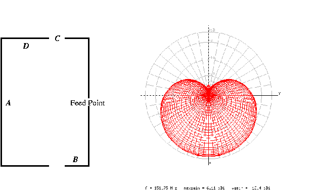
The radiation pattern is shown in the traditional ARRL style and was generated from the final design by xnecview. As the radiation pattern shows, the antenna's gain is confined to nearly a full hemisphere. In other words, it behaves like a high-gain half-omni.
The antenna I build was designed for MURS and was optimized for low SWR, high gain and front-to-back ratio on the first 3 MURS channels. As I intended to construct the antenna from bronze brazing rod, the wire diameter was fixed at 1/8 inches. This resulted in the following geometric parameters:
    A = 27-11/16 in.
    B = 3-15/16 in.
    C = 1-3/8 in.
    D = 5-1/2 in.
    Wire Diameter: 1/8 in
The values in the table above were rounded to the nearest 16th of an
inch. The final .nec file may be found here.
The following image shows the moxon hanging on the rafters of my attic.
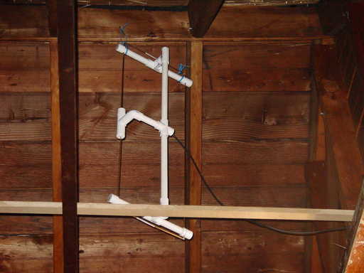
As you can see, the elements are supported by PVC pipe, which also serves as a channel to route the coaxial cable. (The moxon is suspended above the horizontal 1x2 board although it looks as though it is sitting on it.)
The antenna performs quite well on the 2 meter band, even though it was designed exclusively for the lower 3 MURS channels. My guess is that the attic environment has effectively ``electrically-lengthened'' the antenna by a small amount. In fact, the following plot shows the measured values of the SWR of the attic-mounted antenna:
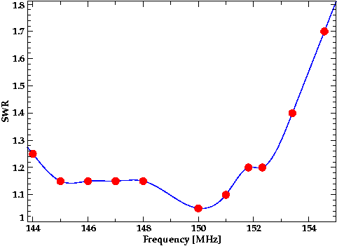
The blue curve is a cubic spline fit to the measured points shown in red.
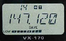
In free space, NEC-2 predicts the gain to be just over 6 dBi with a front-to-back ratio of 40 dBi. I have no instruments that can measure the actual gain of the antenna as mounted in the attic. I can certainly say that it is directional and performs substantially better than my j-pole, which has a gain of somewhere near 3 dBi. For example, the following figure shows the signal strength of a nearby repeater as seen by my j-pole, which is an omnidirectional antenna with about 3 dBi gain:
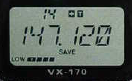
Here is an image of the signal strength of the same source as seen by the moxon pointed in its general direction:
Similarly, here are images showing the signal strength of a source in the roughly opposite direction of the moxon's pointing. The image on the left corresponds to the j-pole and the one on the right corresponds the moxon: